RCATheremin.com
RCA Theremin Instruction Manual
The RCA Theremin Instruction Manual is taken from the printed original and has been carefully digitized so that the text is searchable.
RCA Theremin Musical Instrument
RCA Theremin
Musical Instrument
AC Lighting Circuit Operated
Introduction
RCA Theremin is an electric musical instrument played by the free movement of the hands in space. It opens up new possibilities of expression to musicians, and a new field of enjoyment to all music lovers.
The electrical circuits involved are designed to produce pleasing tone qualities and ample volume of sound. The actual reproduction of these sounds is accomplished by means of a loudspeaker which is to be used with the RCA Theremin. This may be located adjacent to the Instrument or as far away as the artistic effect demands.
The method of playing will soon be mastered by anyone who has a sufficiently good musical ear to either hum or whistle on key. The free movement of the right hand toward one antenna controls pitch and that of the left hand toward the other antenna regulates the strength of the tone produced.
The Instrument operates entirely from the house lighting circuit. On the front of the cabinet two control knobs are provided for adjusting the effect of the antennae to the proper range. A pilot lamp, between the knobs, indicates when the Instrument is turned on. A power switch, mounted on the front of the cabinet, controls the power supply for both the RCA Theremin, and (when used) an RCA Loudspeaker 106. A play-off Switch connects the loudspeaker when the player is ready to begin.
Part I—Installation
Equipment
- One set of Radiotrons as follows:
- Two RCA Radiotrons UX-171-A
- One RCA Radiotron UX-120
- One RCA Radiotron UY-224
- Three RCA Radiotrons UY-227
- One RCA Radiotron UX-280
- Two Mazda No. 40 Pilot Lamps (one spare); T-3 bulb, miniature base, 6 volts, 0.15 amp. (packed in instruction book envelope)
- Loudspeaker—RCA Loudspeaker 106 (Electro-Dynamic) is recommended, although any one of the following may be used in conjunction with an output transformer:
- RCA Loudspeaker 103
- RCA Loudspeaker 100-B
- RCA Loudspeaker 100-A
Preliminary—
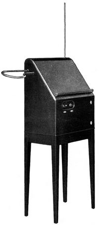
After unpacking the RCA Theremin, open the doors at the back. Unwrap the power cord (see Fig. 1) and bring it out through the hole in the bottom of the cabinet.
The RCA Theremin console should be placed in a position suitable to the audience and the occasion, bearing in mind that metal objects near the antennae interfere with their normal control by the hands of the player. For example, it is not desirable to place the Instrument closer than two feet to a wall containing metal lath or pipes, etc.
The Loudspeaker should be unpacked and installed in accordance with the instructions accompanying the Loudspeaker.
In selecting a location for the Loudspeaker, consideration should be given to the acoustics of the room in which it is placed, as when placing any musical instrument.
Fig. 1. Lower Compartment of RCA Theremin
Pitch Control and Volume Control Antennae—
The Pitch Control and Volume Control Antennae will be found packed in the lower compartment of the RCA Theremin. Unwrap the antennae. The straight rod or Pitch Control Antenna should be placed in its single socket mounting on the console top, and the bent rod or Volume Control Antenna in its mounting on the side of the cabinet with the bulging side toward the musician. (See Fig. 2)
External Connections (See Fig. 1)—
All external connections are made through the hole in the base of the cabinet. The two pin terminals of the loudspeaker (or output transformer) cord should be inserted in the pin jacks in the base of the power unit. When an RCA Loudspeaker 106 is used, the loudspeaker power cable should be plugged into the receptacle in the RCA Theremin cabinet. Safety switches are provided so that there is no voltage on open connections when the cabinet doors are open. These doors must be closed to operate the RCA Theremin.
Loudspeaker Switch—
If RCA Loudspeaker 106 is used, the power switch, located on the side of the loudspeaker cabinet, should be set permanently to the “on” position. The Power Switch on the RCA Theremin then controls both the RCA Theremin and the Loudspeaker.
Power Supply—
The RCA Theremin should never be connected to any circuit supplying other than alternating current, within the rated limits of voltage and frequency (cycles) specified on the license notice on the inside of the cabinet door. Failure to observe this may result in damage to the Instrument. If there is any doubt about the rating of the house lighting circuit, consult the Electric Light and Power Company before connecting the Instrument. (See “Voltage Switch,” Part III.)
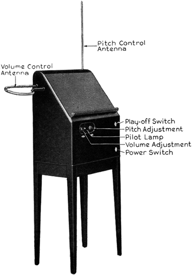
Fig. 2. RCA Theremin Showing Antennae and Controls
Tube Protectors—
The power unit in this Instrument is designed to supply correct voltages to the Radiotrons, without the addition of a tube protector or line voltage reducer. A tube protective device of any kind, used in series with the power supply, will reduce the voltage supplied to the Instrument so that the Radiotrons will not receive their proper voltages, and therefore will not operate at highest efficiency. For this reason, it is recommended that no line voltage reducing device be used with this Instrument.
Important—
Never apply power to the RCA Theremin unless all the Radiotrons are in the sockets.
Radiotrons—
Insert the eight Radiotrons, which should always be handled carefully, in the proper sockets, as shown in Fig. 1 and 3. Be sure that the "UX" Radiotrons are faced so that the two large pins enter the large holes, and that the base of each Radiotron rests squarely against the socket. After the Radiotrons are inserted, press the grid lead cap (see Fig. 3) firmly down over the grid contact of the UY-224 Radiotron.
Pilot Lamp—
Remove the tube supporting the red crystal on the front of the console (see Fig. 2) by gripping it with the fingers and pulling outward. Screw the pilot lamp in place and replace the crystal.
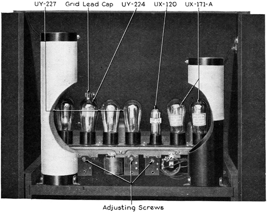
Fig. 3. Upper Compartment of RCA Theremin with Coils Cut Away to Show Radiotrons (Rear View)
Part II—Operation
The RCA Theremin is operated by free movement of the player's hands in space within the electric fields formed by the Instrument around the two antennae.
Changes in pitch are produced by moving the right hand nearer to or away from the Pitch Control Antenna. Moving the hand toward the antenna raises the pitch; moving it away from the antenna lowers it (see Fig. 6 and 7).
Changes in volume are produced by raising or lowering the left hand over the Volume Control Antenna. Bringing the hand nearer the antenna weakens the sound (even to complete inaudibility); moving it away from the antenna, strengthens the sound (see Fig. 8 and 9).
- Set the Power Switch (Fig. 2) to the “on” position, upward. The pilot lamp should light. A few seconds should be allowed for the Radiotrons UY-224 and UY-227 to heat.
Correct Position
The player should take his stand in front of the Instrument at approximately equal distances from the two antennae. It remains for the player to find a posture which he will be able to maintain while playing, as the immobility of the player's body is of great importance. (See Fig. 4.)
The player's distance from the Instrument is determined by his reach. The knuckles of the extended right hand should just reach the Pitch Control Antenna. (See Fig. 5.)
Tuning
Turn both the Volume Adjustment (knob marked “volume”) and the Pitch Adjustment (knob marked “pitch”) to the extreme counter-clockwise position.
Set the upper switch to the position marked “play”. Hold the left hand a few inches above the Volume Control Antenna while making adjustments, in order to avoid sounds that are too loud.
The tuning of this Instrument is not similar to that of any other and consists in:
Setting up the lowest note available when the player stands in the correct position with his right hand comfortably close to the shoulder. (See Fig. 7.) This is produced by a slow clockwise rotation of the Pitch Adjustment with the left hand until the lowest available note is reached.
Turning this control clockwise will contract the scale (move the intervals closer together and the lowest available tone closer to the antenna). Turning the control counter-clockwise will expand the scale (move the intervals farther apart and the lowest available tone farther from the antenna).
Setting up a desired maximum volume. The Volume Adjustment must be set so that the loudest sound desired is obtained when the left hand is about ten inches from the Volume Control Antenna. (See Fig. 9.)
Turning the Volume Adjustment clockwise will increase the maximum volume. Rotating it counter-clockwise will decrease the volume.
Movement of the Hands
It is desirable that the movement of the right hand toward the Pitch Control Antenna should be made along a straight horizontal line. The height at which the right hand is moved does not matter; it is chosen arbitrarily to suit the player's stature. (See Fig. 4.)
The movement of the left hand should be in a vertical direction, above the Volume Control Antenna.
For the position of the wrists of both hands see Fig. 4 to 9 inclusive. The wrists must remain free (relaxed) in all the positions necessary for playing.
Vibrato
Vibrato gives RCA Theremin warmth and expressiveness. The average speed of vibrato which produces a tone of fine quality is about 5 to 6 vibratory movements per second. The hand should move through a distance of about a quarter of an inch, or slightly more, when producing vibrato.
While making these movements, the wrist should remain free, otherwise premature fatigue will result.
The position of the hand is shown in Fig. 6 and 7.
Each distinct vibration is engendered by a double movement of the wrist; first forward toward the Pitch Control Antenna, then back.
Exceedingly deep movements must be guarded against, as the tone then produces an unfavorable impression, while an accelerated vibrato of considerable depth gives the effect of a trill.
After mastering the principles of operation, the player will find himself able to develop variations in technique of his own. The RCA Theremin is admirably adapted to individualism of expression.
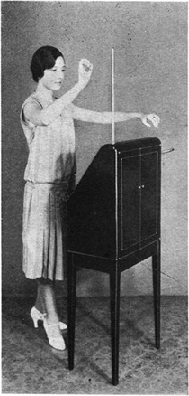
Fig. 4. Correct Playing Posture
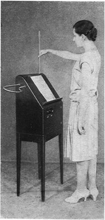
Fig. 5. Determination of Correct Playing Distance
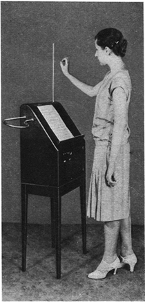
Fig. 6. Right-hand Position for High Pitch Tones
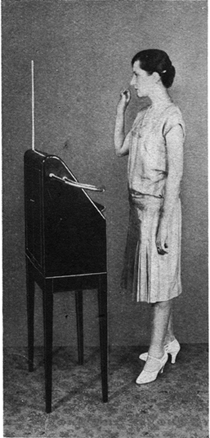
Fig. 7. Right-hand Position for Low Pitch Tones
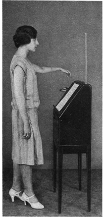
Fig. 8. Left-hand Position for Low Volume
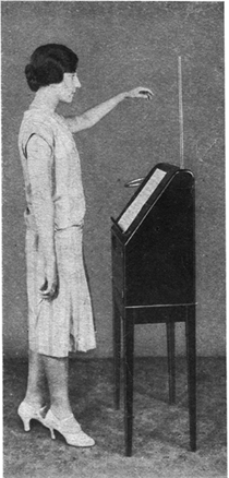
Fig. 9. Left-hand Position for Maximum Volume
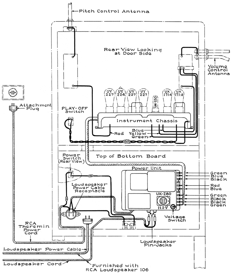
Fig. 10. RCA Theremin Cabinet Wiring
Part III—General Information
The following suggestions are offered to assist the user:
Voltage Switch—
The Voltage Switch of the RCA Theremin is originally set for normal operation on voltages above 115. The original setting should be left unchanged unless it is definitely determined by consulting the Electric Light and Power Company that the supply voltage is normally below this value. Where the line voltage is below 115, improved operation with normal life of the Radiotrons will be obtained if the Voltage Switch is set at the “110 V” position.
The Voltage Switch is accessible by removing the terminal cover (Fig. 1). Before removing the terminal cover, the Power Switch should be set in the “off” position (downward) and left in this position until the terminal cover is replaced.
Important—
The adjusting screws on the back of the chassis (see Fig. 3) are set correctly before leaving the factory and should not be changed.
Power Supply—
In some cases more satisfactory operation may be obtained by reversing the plug at the electrical outlet.
Part IV— Maintenance
Radiotrons—
Before interchanging or removing any Radiotrons from their sockets, the Power Switch should be set to the “off” position.
The contact pins of all Radiotrons, also the grid contact of the UY-224 should be inspected periodically and kept clean.
It is a good plan to have available at least one new RCA Radiotron of each type. Occasionally, the condition of each Radiotron in use should be checked by substituting a new one and comparing results.
Power Supply—
Should the pilot lamp fail to light with the Power Switch in the “on” position, it is probable that the Instrument is not properly connected to the power supply. Make sure that the attachment plug is properly inserted in the electrical outlet and that the current is not switched off at any point.
Loudspeaker—
Poor tone quality may possibly be caused by trouble in the loudspeaker. This can be checked by substituting another loudspeaker. Before interchanging loudspeakers, the Power Switch should be set in the “off” position.
Notice
The apparatus and devices which, or the use of which, are covered by patents are sold only under certain specified licenses set forth in a notice attached permanently to the said devices, or if this is impracticable on account of size, then on tags or wrappers attached to the said apparatus and devices or on the cartons containing the same. The license notice on the RCA Theremin is as follows:
“This device is licensed only for private use in homes as a musical instrument otherwise than in combination or in connection with apparatus in the field of wire telephony; and only where no business features are involved. Not licensed for theatrical or other public or professional performances unless such use is authorized by special, written contract of sale.”
Radio-Victor Corporation of America