RCATheremin.com
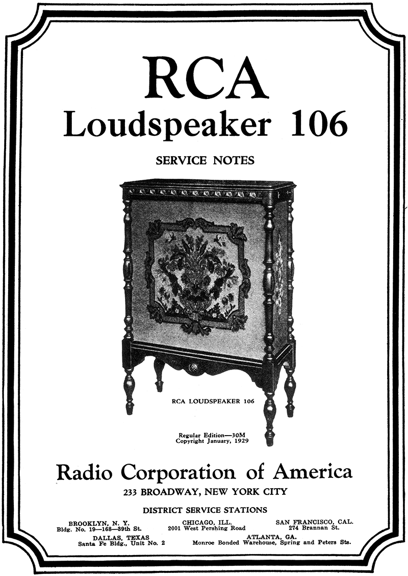
RCA Loudspeaker 106 Service Notes
The RCA Loudspeaker 106 Service Notes document is taken from the printed original and has been carefully digitized so that the text is searchable and the table of contents hyperlinked.
Preface
Service goes hand in hand with sales. The well-informed RCA Authorized Dealer renders service at time of sale in affording information as to proper installation and upkeep. Subsequent service and repair may be required by reason of wear and tear and mishandling, to the end that RCA Loudspeaker and Radiola owners may be entirely satisfied.
Obviously, this service can best be rendered by properly equipped service organizations having a thoroughly trained personnel with a knowledge of the design and operation of RCA Loudspeakers and Radiolas.
Such service organizations have been established by RCA Distributors, and RCA Authorized Dealers are advised to refer any major work or replacement to their selected Distributors. Minor replacements and mechanical and electrical adjustments may be undertaken by the RCA Dealer.
To assist in promoting this phase of the Dealer and Distributor's business the RCA Service Division has prepared a series of Service Notes—of which this booklet is a part—containing technical information and practical helps in servicing RCA Loudspeakers and Radiolas.
This information has been compiled from experience with RCA Dealers and Distributors' service problems and presents the best practice in dealing with them. A careful reading of these Service Notes will establish their value, and it is suggested they be preserved for ready reference.
In addition to supplying the Service Notes, the RCA Service Division maintains a corps of engineers who are qualified to render valuable help in solving service problems. These engineers call upon the trade at frequent intervals to advise and assist RCA Distributors in the performance of service work.
Property of the Radio Corporation of America. Confidential and to be used only by its Authorized Distributors and Dealers in furnishing service in connection with its apparatus.
Copyright 1929—Radio Corporation of America
Contents
Part I—Installation
Part II—Service Data
Part III—Electrical Tests
Part IV—Making Replacements
Illustrations
- RCA Loudspeaker 106
- Rear Interior View
- Schematic Diagram
- Wiring Diagram
- Centering Cone
- Removing Baffle
- Baffle Plate Partly Removed
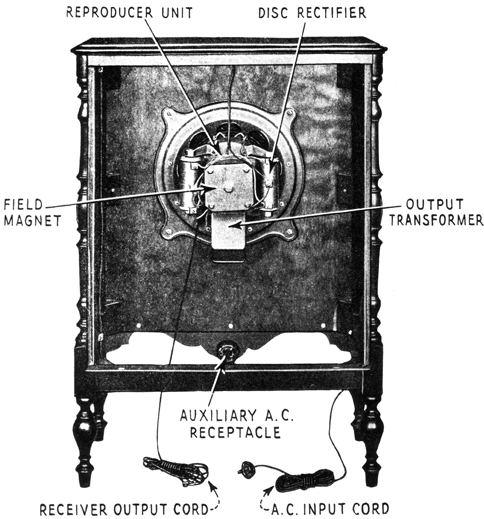
Figure 1—Rear interior view of Loudspeaker 106
RCA Loudspeaker 106
Service Notes
Introduction
RCA Loudspeaker 106 is a reproducing device operating on the electro-dynamic principle and is designed for use with any radio receiver having a power output tube or using an external power amplifier. The entire mechanism is mounted in an artistic cabinet having a large baffle area and an open back. Both of these features contribute materially to the quality of reproduction that is an inherent characteristic of Loudspeaker 106.
The dynamic speaker mechanism consists of an eight-inch corrugated cone, similar to that used in Radiolas 62 and 64, a new type field magnet, a full wave disc rectifier, an output transformer, and two .1 mfd. line condensers. A receptacle is also provided at the rear of the cabinet for connecting the A. C. input current to the receiver used with the Loudspeaker, or any accessories requiring A. C. current for their operation in conjunction with the Loudspeaker. Thus the Loudspeaker operating switch provides complete control over the entire radio installation—a very useful and convenient feature.
Loudspeaker 106 is also made in a model adapted to D. C. operation. This model is similar to the A. C. model except that a higher resistance field is used and no rectifiers nor .1 mfd. line condensers are used. Because of this slight difference the present Service Notes apply equally well to the D. C. models.
Part I—Installation
The following instructions should be observed when installing Loudspeaker 106. Damage to the speaker will result if improperly installed when operation is attempted.
[1] Assembly
- Remove the cabinet from the shipping container and place it front down on a rug or other soft material. Remove the two screws that hold the back cover in place and remove the back cover.
- Place the mechanism assembly in position on the front baffle board as indicated in Figure 1 (output transformer toward the legs). Place the four mounting screws in place and screw down tightly.
- Connect the receiver output leads, the cord that has phone tips, to the two terminals located on the lower side of the reproducer unit. See Figure 1.
- Connect the leads from the top of the cabinet (A.C. input leads) to the two center connections of the disc rectifiers taking care not to allow the wires already connected to these terminals to become disconnected. Do not connect these leads to the two terminals at the top of the frame because it will cause immediate burn out of the cone coil and output transformer and may possibly cause other damage when the current is switched “on.”
- Return the back to the cabinet, allowing the input leads and power cord to fall through the opening in the bottom of the cabinet.
- Connect the A. C. input cord of the receiver, or other device, to be operated simultaneously with the Loudspeaker to the auxiliary receptacle at the back of the Loudspeaker cabinet. If more than one outlet is necessary a two-way plug may be used.
- Connect the two phone tips of the speaker cord to the output from the receiver. Never put the phone tips into the auxiliary receptacle openings.
The operating switches on the receiver and power devices in the installation are left permanently on and the installation is controlled by the operating switch in the Loudspeaker.
Should the receiver use a battery for filament supply the receiver filament switch will also have to be operated in addition to the Loudspeaker operating switch.
A trickle charger and storage battery should not be connected to the auxiliary receptacle, but should be connected to a separate supply outlet and operated according to instructions accompanying the device.
If the receiver is entirely battery operated the auxiliary receptacle is not used.
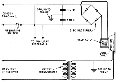
Figure 2—Schematic wiring diagram of Loudspeaker 106
Part II-Service Data
The service problems of Loudspeaker 106 deal with conditions evidenced by no reproduction, weak reproduction and distorted or noisy reproduction. These conditions and their attending causes, while not common to Loudspeaker 106, are explained and remedies noted so that service men may be provided with helpful information in any service work that may be required. Figure 2 illustrates the schematic circuit diagram which will be found useful in connection with service work.
[1] Receiver Output
Before inspecting the Loudspeaker for the cause of any imperfect operation first check the receiver output with a pair of head phones or another loudspeaker known to be in good operating condition. Any distortion in the receiver will be faithfully reproduced in the loudspeaker and corrective remedies must be applied to the receiver. However, if a signal of good quality and volume is being delivered by the receiver, the Loudspeaker must he examined for the trouble experienced.
[2] No Output
If the receiver output is O.K. and no reproduction is delivered by the Loudspeaker look for:
- Open winding of output transformer.
- Shorted connections to output transformer.
- Open cone coil.
- Shorted or grounded cone coil.
- Defective input cord or faulty connections, either at receiver or loudspeaker.
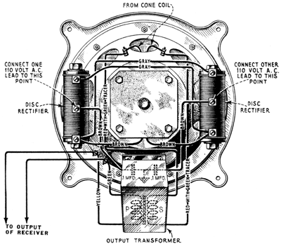
Figure 3—Wiring diagram of reproducer unit
[3] Weak Signals
Should weak signals be experienced check the following:
- Open or shorted field coil. A short my be experienced at the point where the leads enter the field magnet housing.
- Defective disc rectifier. A defective rectifier—not supplying field current—will cause weak reproduction. This will generally be accompanied by a loud hum. Sometimes the fuses in the A. C. line will blow.
- Defective connections to rectifier or to field, or a defective operating switch. Check all connections carefully against the wiring diagram Figure 3.
[4] Distorted Or Noisy Reproduction
Distortion or noise may be caused by any of the following conditions:
- Cone out of alignment. Remove reproducer unit as explained in Part IV, Section 1. Then center the cone as described in Part II, Section 6.
- Leads from cone coil broken away from side of cone. Remove reproducer assembly as described in Part IV, Section 1, and fasten the leads to the side of the cone with a little shellac.
- Loose name plate, rear panel or any cabinet parts will cause a rattle at certain frequencies. Tighten all loose parts.
- Open or shorted line condensers. Defective line condensers may allow the receiver to be affected by R. F. noise originating in the disc rectifiers. If both line condensers should become shorted, the fuses in the A. C. line will probably blow.
[5] Hum
Excess hum and faulty operation may be caused by defective disc rectifiers. This may be checked by measuring the voltage across the terminals of the field leads. With the field connected it should be about 80 volts and with the field disconnected about 95 volts. The receiver should also be checked for excessive hum. A receiver that will operate satisfactorily with a magnetic type of Loudspeaker may have an excessive amount of hum when operated with a dynamic speaker. This is due to the greater low frequency response of the dynamic speaker compared with the magnetic. When this condition exists the remedy must be applied to the receiver, not the Loudspeaker.
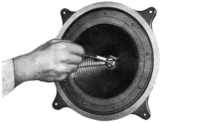
Figure 4—Centering cone
[6] Centering Reproducer Cone
To properly center a new cone or one out of center use the following procedure:
- Remove the reproducer assembly from the cabinet as described in Part IV, Section 1.
- Loosen center screw of cone, but do not remove it.
- Insert three cardboard strips, about the thickness of a visiting card, 1 1/2 inches by 1/4 inch in size, through the center spider of the cone into the space between the pole piece and cone coil. This will give the cone coil the same clearance on all sides of the pole piece.
- Tighten the center screw (Figure 4) holding the spider of the cone and remove the three strips. The cone is now properly centered. Replace the reproducer assembly in the cabinet in the reverse manner of that used to remove it.
Part III Electrical Tests
The following tests give complete check on the circuits of Loudspeaker 106 and should be referred to whenever the functioning of the speaker is faulty in order to locate the cause.
[1] Testing The Disc Rectifier
The disc rectifier may be checked by measuring the output voltage that is delivered to the field of the reproducer unit. This should be approximately 80 volts with the field connected; with the field disconnected it should rise slightly to about 95 volts.
Precaution—The operation of the disc rectifier depends on the pressure with which the discs are held. Do not loosen the bolts that hold them together as it is highly improbable they can be returned to normal operation without special instruments. Should replacement become necessary, remove the bracket and the unit together. The replacement part is supplied with brackets so that replace ment is comparatively easy.
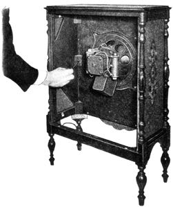
Figure 5—Removing baffle plate
[2] Testing Output Transformer
The primary of the output transformer should be tested for continuity by click testing from the phone tips that connect to the receiver output terminals. While testing shake the cord so that any intermittent opens may be disclosed. If this tests O.K. remove the cord from the two terminals and then test the cord for a short by shaking. After testing the cord test from terminal to terminal at the cord connections on the reproducer frame. This should test closed. Then test from each terminal to ground. The primary should not be grounded. The secondary winding of the transformer should then be tested by removing the two leads from the cone coil and testing from terminal to terminal. This should test closed. Then test from each terminal to ground. One side of the secondary is grounded so a click will be obtained when either of the terminals are tested to ground.
Disconnect the transformer leads from their terminals and check to determine that only one terminal is grounded. If both are grounded to frame one should be re-insulated with new insulating washers.
[3] Testing Cone And Field Coil
Disconnect the two cone coil leads from their terminals on the reproducer frame and test from terminal to terminal. It should test closed. Then test to ground. It should not be grounded.
The two field coil leads should be disconnected from the rectifier and a test made from lead to lead. It should test closed. The field coil is not grounded.
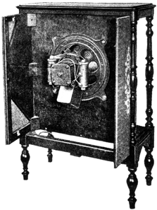
Figure 6—Baffle plate partly removed
[4] Testing Line Condensers
The two line condensers may be tested by releasing their two outside leads (Figure 3) and testing from each lead to frame. They should test open. A shorted condenser will necessitate a replacement of the whole unit including the output transformer.
After all testing is completed and the necessary repairs are made, all wiring should be returned to its proper place as indicated in Figure 3.
Part IV—Making Replacements
The reproducer assembly and cabinet parts in Loudspeaker 106 are easily accessible and replacements can be made readily. The following procedure outlines the methods to be used when making replacements.
[1] Replacing Parts In Reproducer Assembly
To replace a part in the reproducer assembly proceed as follows:
- Remove rear panel by unscrewing the two wood screws that hold it in place and lift the panel clear.
- Disconnect the A. C. input connections to the disc rectifier, having previously removed the A. C. input plug from the supply outlet.
- Disconnect the receiver output leads at their terminals on the reproducer frame.
- Remove the four bolts that hold the reproducer assembly to the baffle board. It may now be lifted clear and placed in a position convenient for work. After the necessary repairs or replacements are made, it should be returned in the reverse manner of that used to remove it.
[2] Replacing Grille Cloth
The grille cloth used in Loudspeaker 106 is supplied in one piece consisting of the front and two sides stitched together. Should replacement become necessary proceed as follows:
- Remove rear cover by removing two wood screws and lifting clear.
- Remove all connections to reproducer assembly and release the A. C. input cable from the sides of the cabinet. Then release the operating switch and the auxiliary receptacle and pull cable, switch and receptacle through opening in bottom of cabinet.
- Remove the eighteen wood screws (Figure 5) that hold the baffle and side pieces to the cabinet frame. The frame may now be pulled through the rear opening (Figure 6). The grille cloth is held in place by means of tacks. Remove the tacks and grille cloth and stretch the new cloth in place. Replace the tacks.
- The cabinet is then reassembled in the reverse manner of that used to disassemble it and the Loudspeaker is returned to normal operation.
[3] RCA Loudspeaker 106 Replacement Parts
- No. Description
- 5895 Tapestry — Grille Cloth—Comprising front and side pieces stitched together.
- 2361 Output Cable — From receiver to loudspeaker.
- 5896 Power Cable — From socket outlet to operating switch, power receptacle and disc rectifier.
- 2015 Switch — Line operating switch.
- 5898 Rectifier Stack.
- 5899 Transformer — Comprising output trans former and two capacitors mounted in metal container.
- 8375 Cone — 8" Corrugated paper cone.
- 8376 Ring — Metal clamping ring for holding cone.
- 8390 Ring — Cardboard seal ring—Package of 10.
- 8391 Coil — Field Coil.
- 9248 Magnet complete — Comprising field coil, core, coil case, two end plates, cone sup port, paper washers, four machine bolts with nuts and one cap screw.
- 5980 Field Coil (D. C. Model).
- 5981 Transformer — Output Transformer (D. C. Model).
- 5982 Terminal Strip Assembly — Comprising metal bracket with insulating bushings inserted, dilecto strips top and bottom, terminal screws with nuts and washers—completely assembled (D. C. Model).
- 9276 Magnet complete with Cone Support — Comprising two end plates, coil easing, core, field coil, damping washer, cone support, paper washers, four machine bolts with lock washers and nuts and one cap screw for holding core—completely assembled (D. C. Model).
Service Data ChartThe following table of information provides a handy reference when servicing Loudspeaker 106 and a working knowledge of it will enable service men to handle service problems readily and efficiently. Reference to Part No. and Section No. in the “Service Notes” is noted for detailed information. |
||
|---|---|---|
| Indication | Cause | Remedy |
| No Reproduction | No output from receiver | Examine receiver, Part II, Sec. 1 |
| Defective cone coil | Replace cone | |
| Defective output transformer | Replace output transformer | |
| Defective cord | Repair or replace cord, Part III, Sec. 2 | |
| Loose or broken connections | Repair connections, Part III, Sec. 2 | |
| Weak Reproduction | Weak receiver output | Examine receiver, Part II, Sec. 1 |
| Improperly centered cone | Center cone correctly, Part II, Sec. 6 | |
| Open field | Replace field coil, Part III, Sec. 3 | |
| Defective rectifier | Replace rectifier, Part III, Sec. 1 | |
| Faulty connections | Repair connections, Part II, Sec. 3 | |
| Distorted or noisy Reproduction (Rattle) | Distorted output from receiver | Examine receiver, Part II, Sec. 1 |
| Improperly centered cone | Adjust cone correctly, Part II, Sec. 6 | |
| Cone leads broken from side of cone | Fasten loose leads with shellac, Part II, Sec. 4 | |
| Open or shorted line condensers | Replace defective condensers, Part II, Sec. 4 | |
| Loose parts in cabinet assembly | Tighten all loose parts or nuts, Part II, Sec. 4 | |
| Hum | Faulty receiver output | Check receiver output for hum and make repairs necessary, Part II, Sec. 5 |
| Defective disc rectifier | Replace defective rectifier, Part III, Sec. 1 | |