RCATheremin.com
RCA Theremin Service Notes
The RCA Theremin Service Notes document is taken from the printed original and has been carefully digitized so that the text is searchable and the table of contents hyperlinked. Like the pdf we offer, the errors in the “SPU Terminal Strip Voltages” table and the tube numbering in fig. 4 have been corrected.
Preface
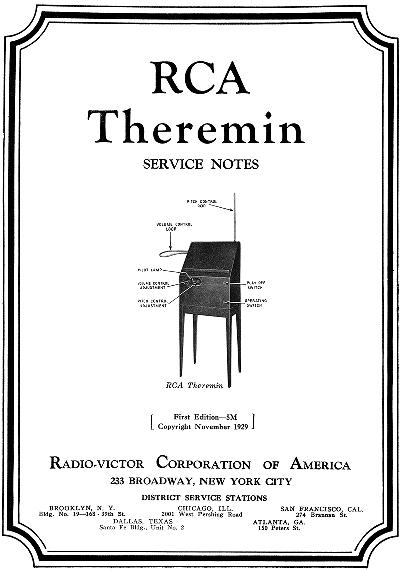
The RCA Theremin is an electrical musical instrument played by the free movement of the hands in space. The actual production of sound is accomplished by means of a loudspeaker which must be connected to the RCA Theremin. The loudspeaker may be located close to the Theremin or at any convenient distance as required.
The electrical circuits incorporated in the instrument are designed to operate from the house lighting circuit controlled by a power switch mounted on the cabinet. Provision is also made for adjusting pitch and volume by suitable panel controls. A “play-off” switch provides for turning “On or Off” the Theremin with switching off the power supply.
A knowledge of the design and operation of the instrument is desirable if any service work becomes necessary. The present RCA Service Notes have been prepared to provide service personnel with practical help and technical information in the performance of this service work. This information has been compiled from experience with the problems encountered and presents the best practice in dealing with them. A careful reading of these Service Notes will establish their value and it is suggested they be preserved for ready reference.
In addition to supplying the Service Notes RCA maintains a corps of engineers who visit the trade at frequent intervals to advise and assist in the performance of Service Work.
Property of the Radio-victor Corporation of America. Confidential and to be used only by those authorized by RCA to furnish service in connection with its apparatus.
Copyright 1929—Radio-victor Corporation of America
Contents
Part I—Service Data
- Installation
- Normal Operation
- Volume Control Adjustments
- Pitch Adjustment Condenser Not at Center
- Range Below 1100 Cycles
- Reversed Action of Pitch Control
- High Pitched Note
- Skip Effect In Pitch Control
- Service Data Chart
- S.P.U. Terminal Strip Voltages
- Theremin Radiotron Socket Voltages
- Methods for Continuity Tests
- S.P.U. Continuity Tests
- Main Assembly Continuity Tests
Part II—Making Replacements
Illustrations
- RCA Theremin
- Rear Interior Cabinet View
- Top Chassis View of the Main Assembly
- Sub-Chassis View of the Main Assembly
- Schematic Circuit Diagram of the Main Assembly
- Schematic Circuit Diagram of the Socket Power Unit
- Complete Layout and Cable Connections to the Various Assemblies
- Wiring Diagram of the Socket Power Unit
- Wiring Diagram and Parts of the Main Assembly
- Internal Connections of Filter And By-Pass Condensers, and Filter Reactor
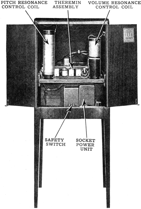
Figure 1—Rear interior cabinet view
RCA Theremin Service Notes
Electrical Specifications
Physical Specifications
Introduction
The RCA Theremin is a musical instrument operating entirely on electrical principles and played by the movement of the hands in space. Having no limitations such as key boards, stops, etc., exceptional individuality of expression may be obtained. The instrument covers approximately three and one half octaves, the highest note being about 1400 cycles. Figure 1 illustrates a rear interior cabinet view and Figures 2 and 3 a top and bottom chassis view of the main assembly. The operation of this instrument is covered in the instruction book accompanying each RCA Theremin.
The principle of operation of the RCA Theremin is that of the beat frequency oscillator. The frequency of one oscillator may be varied by the capacity change caused in an associated circuit by the movement of the hand to or from a pitch control rod. Also an additional oscillator provides radio frequency current for heating the filament of a UX-120 arranged so as to control the volume of output, this control being due to the movement of the hand in relation to the volume control loop. A detailed description of the functioning of the various circuits follows:
Electrical Description Of Circuits
As stated in the foregoing, the musical note of the RCA Theremin is produced by two oscillators of slightly different frequency beating together. This beat note is then amplified by two audio stages. The change of note caused by the movement of the hand is due to the change of capacity across what is known as the pitch coil, this slight change having sufficient effect on an adjacent oscillator circuit to change the frequency and thus the beat note, the amount of change depending on the position of the hand in relation to the pitch control rod.
Referring to the schematic circuit Figures 4 and 5 and starting from the pitch control rod we find the circuits functioning as follows :—
The pitch control rod is connected to a coil having a very high inductance. Connected to this coil is a small condenser and a small concentrated coil. This entire circuit is tuned by the distributed capacity of its coils and resonates at approximately 172 K.C. Not having any fixed capacitor connected across it for tuning, the ratio of inductance to capacitance is very high. Thus the small increase of capacity caused by the hand close to the pitch rod will cause the circuit to change its natural period considerably, a great deal more than if a large capacity and small inductance were used.
This pitch control circuit is connected to the grid side of the variable pitch control oscillator the frequency of which is slightly greater than that of the pitch control circuit. Bringing the hand close to the pitch rod will increase the parallel capacity in that circuit and thus reduce its frequency. As this capacity is reflected in the oscillator circuit a similar decrease in frequency will result in that circuit, the amount of decrease depending on the closeness of the frequency of the two circuits. Thus a greater decrease in frequency of the oscillator circuit is obtained when the pitch control circuit is close to the oscillator circuit in frequency than when it is at a greater frequency difference.
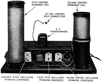
Figure 2—Top chassis view of the main assembly
The next circuit to examine is the fixed pitch oscillator. This circuit oscillates at a frequency, when correctly adjusted, at a maximum of 1400 cycles greater than the variable pitch oscillator. The amount of this difference is dependent on the frequency of the variable pitch oscillator the frequency of which is determined by the position of the hand in relation to the pitch control rod. The frequency of the fixed pitch oscillator does not change while playing.
An example of the functioning of these three circuits follows :—
The hand approaches the pitch control rod and increases the capacity across the pitch control circuit. This capacity is reflected across the variable pitch control oscillator and thus reduces its frequency. This causes an audible frequency difference between this oscillator and the fixed pitch oscillator, the frequency of this note depending on the position of the hand. Bringing the hand close to the rod will increase the capacity in the pitch control circuit, reduce the frequency of the variable pitch oscillator and increase the difference between the frequency of this oscillator and the fixed pitch oscillator. Thus an audible note is obtained, the note increasing in frequency as the hand approaches the pitch control rod.
Examining the circuit diagram we find that each oscillator grid is connected to the control and screen grid respectively of a Radiotron UY-224. As the screen grid has the largest area, a 10,000-ohm resistance is connected in series with it to balance the input to this tube and have each oscillator have the same effect on the detector action. This tube is a detector or combining tube that functions much in the same manner as the first detector in a super-heterodyne circuit. The output of the detector is then amplified by a two-stage audio frequency amplifier, the output of which goes to the loudspeaker.
The remaining two tubes, Radiotron UX-120 and UX-171A together with the first audio frequency amplifier constitute the volume control system. Examining the UX-171A we find that it is in an oscillating circuit that oscillates at about 420 K.C. Connected to the grid side of the oscillator is the volume control loop circuit. This circuit resonates at a frequency below the oscillator frequency when the hand is entirely removed from the volume control loop. This is done for two reasons. If the two circuits were in exact resonance, the load on the oscillator would be too great and operation would be unstable. Also the pick-up current would be high and might damage the tube. The ratio of inductance to capacity in this circuit is also quite high. A small pick-up coil is wound around the inductance coil of the volume control loop circuit and when both circuits are nearly in resonance (hand entirely removed) sufficient radio frequency current flows in this pick-up coil to light the filament of the Radiotron UX-120 to which it is connected. If the plate supply circuit to the Radiotron UY-227, that is the first audio frequency amplifier, is examined we see that the current for this tube is fed through the UX-120. Thus if the UX-120 were at maximum brilliancy, maximum volume would be obtained. Likewise. if it were not lighted no signal output would be obtained due to no plate current flowing.
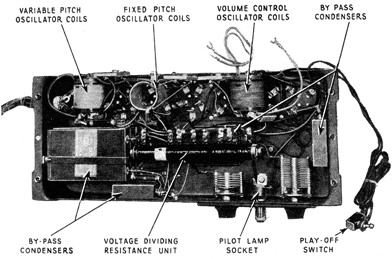
Figure 3—Sub-chassis view of the main assembly
A condenser and resistor are placed in the plate voltage supply to the first audio tube which regulates the time constant of the volume control. They are adjusted to prevent any undue lag in operation of the volume control, while preventing quick accidental variations in volume due to a slight unsteadiness of the hand. The condenser also increases the efficiency of the audio amplifier by preventing a loss of A.C. voltage across the Radiotron UX-120. The low side of the resistance instead of being connected to ground is connected to a tap on the grid leak of the volume control oscillator. This supplies a small negative potential to the plate of the first audio tube and insures that zero volume is secured when the UX-120 emission is zero or nearly so.
Now getting back to the oscillator circuit that lights the filament of the UX-120 we see that if the load current is reduced, the brilliancy of the UX-120 will be decreased and likewise the volume. Thus when the hand approaches the volume control loop, the natural period of the circuit is decreased in frequency, the circuit is out of resonance with the oscillator by an amount depending on the position of the hand and less current is flowing in the pick-up coil with a consequent reduction in volume.
Thus we see from the foregoing explanation, a movement of one hand in relation to the pitch control rod will cause a variation in pitch and thus allow the playing of music. A movement of the other hand in relation to the volume control loop will cause an increase or decrease in volume. The combination of these two movements constitutes the technique of playing the RCA Theremin.
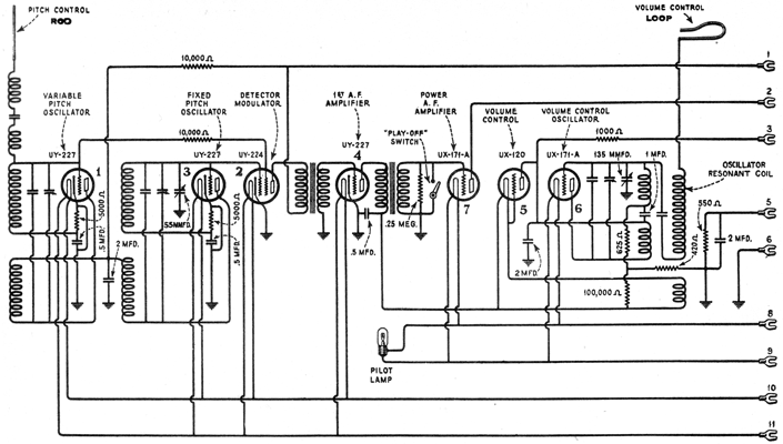
Figure 4—Schematic circuit diagram of the main assembly
Part I—Service Data
(1) Installation
The necessary instructions for installing the RCA Theremin are contained in the instruction book that accompanies each instrument. The notes on location with regard to metal objects and all other points should be carefully checked, as satisfactory operation depends on correct installation.
(2) Normal Operation
Normal operation of the RCA Theremin may be checked in the following manner :—
- Place the Theremin in operation by turning “On” the operating switch, turning the “Play-Off” switch to “Play” and making sure the rear doors are closed.
- Stand erect directly in front of the Theremin so that the body is at a distance from the cabinet determined by placing the right arm straight out from the shoulder with the hand closed. In this position the hand should just reach the pitch control rod.
- Now pull the right arm back to the shoulder. The Theremin should just approach zero beat in this position when the pitch adjustment condenser is at its mid-position. If zero beat is not obtained adjust the pitch adjustment until it is obtained with the hand in this position. Now extend the hand until it is one inch from the pitch antenna. At this point a note of from 1100 to 1400 cycle’s should be obtained. This may be checked with a piano. C sharp, two octaves above middle C is 1096 cycles and F sharp, two octaves above middle C is 1463 cycles. If these conditions are not fulfilled or the pitch adjustment condenser is not in the center, adjust as described in Part I, Section 4.
The volume control may be checked as follows :—
- With the Theremin in operation and an audible note obtained, a good loud signal should be obtained with the hand entirely removed from the volume control loop and the volume control adjustment at maximum (To the right). Placing the hand close to the volume control loop should reduce the volume and give complete cut-off when the hand is three inches above the loop and the volume control adjustment is at maximum. If cut-off is not obtained until the hand is closer or at a greater distance, an adjustment such as described in Part I, Section 3, must be made.
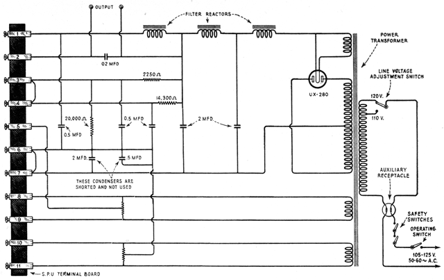
Figure 5—Schematic circuit diagram of the socket power unit
(3) Volume Control Adjustments
Should normal operation of the volume control not be obtained proceed as follows :—
- Volume control cuts off when the hand is at a greater distance than three inches from the loop, the volume adjustment condenser being to the extreme right or maximum position. Also full volume is not obtained when the hand is completely removed. The remedy in this case is to increase the capacity of the volume control oscillator trimming condenser. This condenser is the extreme right one when looking at the Theremin from the rear with the doors open.
- Volume control cuts off when the hand is less than three inches from the loop, the volume adjustment condenser being at maximum. The remedy in this case is to reduce the capacity at the volume control trimming condenser on the rear of the chassis until a normal condition is obtained.
- Volume control has reversed action or goes from low volume to high and then low while the hand approaches the loop. This is due to being on the wrong side of the resonance curve or in the latter condition going from one side of resonance through resonance and then to the other side. The remedy in both cases is to reduce the capacity at the volume control oscillator trimming condenser until normal operation is secured.
- A more accurate method of adjusting the volume control is by the use of a milliammeter. An adapter is necessary, which may be either a UY or UX type and having means for breaking the plate circuit. This adapter may be placed either in the UX-120 socket in the case of the four-prong UX type or in the first audio UY-227 socket. A 0-5 milliammeter is placed in series with the plate of either tube through the connections provided in the adapter. The volume adjustment on the front of the Theremin is then set at maximum. The right rear door is now opened, the safety switch held down with one hand and the volume control oscillator trimming condenser adjusted until the milliammeter indicates 2 M.A. is flowing with door closed. The pitch should be around zero beat when making this adjustment. This is the correct adjustment provided the effect noted in (c) is not obtained, in which case the capacity should be reduced until another reading of 2 M.A. is obtained. Thus the correct adjustment is found when the milliammeter reads 2 with the least capacity at which such a reading may be obtained.
(4) Pitch Adjustment Condenser Not at Center
If the conditions indicated in Part I, Section 2 are fulfilled but with the pitch adjustment condenser off center, it may be corrected as follows :—
- If the pitch adjustment is too far to the right, indicating too much capacity, the remedy is to increase the capacity of the fixed pitch oscillator trimming condenser located on the rear of the chassis. This is the center of the trimming condensers.
- If the pitch adjustment is too far to the left, indicating too little capacity, reduce the capacity of the fixed pitch oscillator trimming condenser.
Both of these adjustments must be made by changing the trimming condenser a little at a time, closing the rear doors and checking from the front for normal operation.
(5) Range Below 1100 Cycles
This indicates the fixed pitch oscillator and variable pitch oscillator are at too great a frequency difference from the pitch control circuit. The remedy is to increase both the fixed pitch oscillator and the variable pitch oscillator trimming condensers until the necessary high note is obtained. These are the left and center trimming condensers respectively at the rear of the Theremin. Care should be taken not to adjust the oscillators so that the note will be higher than 1400 cycles, as unstable operation may result. 1100 cycles is about C sharp, two octaves above middle C, and 1400 cycles about F sharp, two octaves above middle C on a piano. A tuning fork or piano—if available—can be used for a pitch standard. A reversal of connections to the concentrated coil located inside of the large tone coil will also reduce the range of the Theremin.
(6) Reversed Action of Pitch Control
This condition is caused by the fixed pitch oscillator being at a lesser frequency than the variable pitch oscillator. Such action is caused by the fixed pitch oscillator trimming condenser having too much capacity, the variable pitch oscillator having too little capacity or both. The remedy is to decrease and increase the capacity of the respective trimming condensers until normal operation is secured.
(7) High Pitched Note
Should the Theremin give a high pitched squeal when no one is close to it the fixed pitch oscillator trimming condenser is adjusted to too great a capacity. Also too small an amount of capacity at the variable pitch oscillator, or both maladjustments, will cause the condition represented by the effects noted in Section 6—only to a lesser degree. Also this condition may be caused by the two pitch oscillators being too close to the frequency of the tone coil. This is caused by too much capacity at each of the two pitch oscillator trimming condensers. An open tone coil will cause a constant high frequency note with little variation caused by various positions of the hand in relation to the pitch control rod.
(8) Skip Effect In Pitch Control
A pitch control abruptly changing from one frequency to another, instead of giving a smooth variation of tone indicates a poor Radiotron UY-227 in one of the pitch control oscillators. Usually in the three Radiotrons UY-227 used with each Theremin, there will be found two that will function satisfactorily in the pitch oscillator sockets. An erratic UY-227 in the oscillator socket will probably function normally as an audio amplifier. Too much capacity at each of the trimming condensers on the pitch oscillators may cause a skip effect in the range in addition to a greater than normal range. The effect noted in (7) may also be noted.
(9) Service Data Chart
| Indication | Cause | Remedy |
|---|---|---|
| Radiotrons Fail to Light | No supply voltage | Test with A. C. voltmeter at loud- speaker auxiliary power receptacle (operating and safety switches should be closed) |
| Defective safety switch | Test as above. Repair or replace | |
| Defective operating switch | Test as above. Replace | |
| Defective Power Transformer | Check by continuity tests (Section 13). Replace | |
| Defective Radiotrons | Replace | |
| UX-120 (only) fails to light | Low emission UX-280 or 171-A (No. 6) tube not oscillating. (A Neon glow lamp—such as the Cooper Hewitt type G10, 115-V--is a convenient test for oscillation. The brass base of the lamp should be held in the hand and the glass bulb near the pitch control rod or volume control loop). Circuits out of adjustment | |
| Defective wiring | Check by means of continuity tests, Sections 12-13 | |
| Tubes light—Theremin fails to play | Defective "Play-Off" switch | Replace |
| Loudspeaker defective or disconnected | Connect O. K. speaker | |
| 1 Tube Nos. 1, 3, or 6 not oscillating | Test tubes and continuity of circuits, Section 12 | |
| Defective audio input transformer | Check with continuity test | |
| Grounds or opens | Check continuity Sections 12-13 | |
| Control grid connection open at UY-224 | Attach contact cap | |
| Distorted Reproduction | Low emission or defective Radiotrons | Replace |
| Poor wave form of A. C. supply current | Try resistances of from 500 ohms to 2000 ohms in series with control grid of UY-224 | |
| Open 550-ohm resistor | Replace | |
| Defective audio transformer | Replace | |
| Open or imperfect chassis ground | Repair | |
| Improper voltages at audio sockets | Check with tables Sections 10-11, Isolate trouble by continuity test Section 12 | |
| Defective Loudspeaker | Replace | |
| Hum | Defective Radiotrons | Replace |
| Open or shorted center tapped fixed condensers | Repair or replace | |
| Open by-pass or filter condensers | Test and replace | |
| Shorted filter reactor | Check by resistance measurement Replace | |
| Open chassis grounds | Check from diagrams Figures 7-8 | |
| Loose laminations in power transformer | Repair or replace |
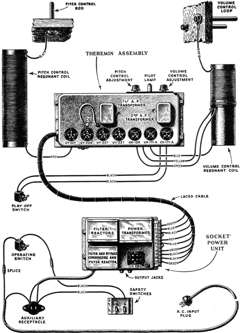
Figure 6—Complete layout and cable connections to the various assemblies
(10) S.P.U. Terminal Strip Voltages
Line 120 volts—Adjustment switch in 120-volt position
Use D.C. voltmeter with a 0-300 volt scale and at least 1,000 ohms per scale volt such as incorporated in Weston Model 537, Type 2, test set, for the D.C. voltage. The A.C. voltage may be measured with an A.C. voltmeter of suitable range. Refer to Figure 6.
| Terminals Nos. | Cable on Tubes Lighted Volts | Cable Off Volts |
|---|---|---|
| 1 to 6 (D.C.) | 190 | 260 |
| 2 to 6* | 190 | 260 |
| 3 to 6 | 140 | 230 |
| 5 to 6 | 29.0 | 0 |
| 8 to 9 (A.C.) rms | 4.7 | 5.0 |
| 10 to 11 (A.C.) rms | 2.5 | 2.8 |
* With Model 106 Loudspeaker connected to audio output pin jacks.
(These jacks may be shorted together for the purpose of taking a reading with negligible error in the result).
(11) Theremin Radiotron Socket Voltages
Line 120 volts—Adjustment switch in 120-volt position
The following voltages taken at each Radiotron socket with the Theremin in operating condition should prove of value when checking with test sets such as the Weston Model 537, Type 2, or others giving similar readings. The plate currents shown are not necessarily accurate for each tube, as the cable in the test set will cause some circuits to oscillate, due to its added capacity. Small variations of voltages will be caused by different tubes and line voltages. Therefore the following values must be taken as approximately those that will be found under varying conditions. Refer to Figure 6.
| Tube No. | Cathode to Grid Volts | Cathode to Screen Grid Volts | Cathode to Plate Volts | Plate Milamps | Filament or Heater Volts |
|---|---|---|---|---|---|
| 1 UY-227 | 11.5 | — | 60. | 7.1 | 1.95 |
| 2 UY-224 | 11.5 | 10.2 | 135. | 0 | 1.95 |
| 3 UY-227 | 11.0 | — | 60. | 5.5 | 1.95 |
| 4* UY-227 | 0 | — | -2 to 40 | 0 to 3.5 | 1.95 |
| 5* UX-120 | 0 | — | 110 to 64 | 0.5 to 4.1 | unreadable |
| 6* UX-171A | 26 to 31 | — | 95. | 12 to 17 | 4.6 |
| 7* UX-171A | 25 to 30 | — | 140 to 145 | 26 to 30 | 4.6 |
* The range of variation of the readings taken on Radiotrons Nos. 4, 5, 6 and 7 is caused by a change in the resonance point of the volume control loop circuit. Any object (such as the measuring instrument cable, body of the operator, etc.) coming in proximity to this circuit will give the variations noted above.
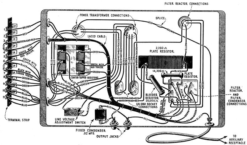
Figure 7—Wiring diagram of the socket power unit
(12) Methods for Continuity Tests
In making a continuity test whether it be for the Theremin assembly or the S. P. U., the following procedure is recommended :—
Disconnect the cable connecting the socket power unit to the Theremin assembly, the loudspeaker, and the A.C. supply cord at its outlet.
A pair of headphones with at least 4 1/2 volts in series, or preferably a voltmeter with sufficient voltage to give a full scale deflection when connected across the battery terminals should be used in making these tests, for example, a 0-50 volt meter with a 45-volt “B” battery. The Radiotron socket contacts, numbers and lugs used in these tests are shown in Figure 6. The Theremin continuity wiring diagram is illustrated in Figure 8. The S. P. U. terminal numbers are shown in Figure 7.
Test leads should be of the flexible insulated type with partially insulated testing tips, so that false readings will not be obtained through contact with the hands. Similarly the hands should not touch the chassis or component parts.
The contacts of the test equipment should be placed across the terminals or leads indicated in the following test table under the column marked “Terminals.” If the results are negative the cause of such negative effect will be found in the last column under the heading, “Incorrect Effect Caused By.” The second column indicates the approximate correct resistance in ohms of most of the circuits tested.
(13) S.P.U. Continuity Tests
Remove UX-280 Radiotron and Disconnect Cable —Refer to Figure 8
| Test Terminals | Correct Effect | Incorrect Effect | |
|---|---|---|---|
| Indication | Caused by | ||
| Terminal No. 1 to filament of rectifier socket | 1000 ohms | Open | Open reactor |
| No. 1 to No. 7 | 22,000 ohms | Shorted | Shorted filter condenser |
| No. 2 to one loudspeaker pin jack | Closed | Open | Open lead |
| No. 2 to other pin jack | Open | Closed | Shorted 0.02 condenser |
| No. 3 to No. 4 | Shorted | Open | Open connection |
| No. 3 to No. 1 | 2500 ohms | 14,000 ohms | Open 2250-ohm resistor |
| 2250 ohms | Open 14,300-ohm resistor | ||
| No. 3 to No. 6 | 20,000 ohms | Open | Open 20,000-ohm resistor |
| Shorted | Shorted 0.5 mfd. condenser | ||
| No. 5 to No. 8 or 9 | 13 ohms | 25 to 30 ohms | Open power transformer winding |
| No. 6 to No. 10 or 11 | 13 ohms | 25 to 30 ohms | Open power transformer winding |
| No. 7 to either plate contact of rectifier socket | 190 ohms | Open | Open connection or open winding in power transformer |
| No. 8 to No. 9 | Shorted | 60 ohms | Open 5-volt filament winding |
| No. 10 to No. 11 | Shorted | 60 ohms | Open 2.5-volt filament winding |
| Across contacts of auxiliary power receptacle | 3 to 6 ohms | Open | Open primary of power transformer or open 110-120-volt switch |
| Across blades of AC input plug with auxiliary receptacle shorted | Closed | Open | Open operating switch, open safety switch, open lead or connection |
| From either contact of auxiliary receptacle to frame | Open | Closed | Grounded primary in power transformer |
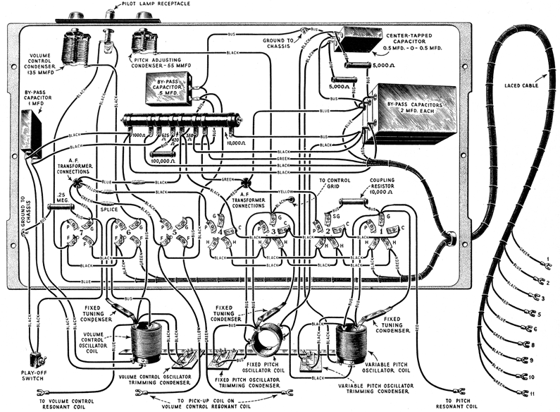
Figure 8—Wiring diagram and parts of the main assembly
(14) Main Assembly Continuity Tests
Remove Radiotrons and disconnect cable—Refer to Figure 8—A D.C. voltage is used in making the tests and the resistance values given are D.C. Plate
| Circuit | Test Terminals | Correct Effect | Incorrect Effect | |
|---|---|---|---|---|
| Indication | Caused By | |||
| Grid | G1 to frame | 5000 ohms | Open | Open No. 1 oscillator coil or 5000-ohm resistor or both |
| 3 ohms | Shorted 0.5 mfd. condenser | |||
| Control grid No. 2 or G3 to frame | 5000 ohms | Open | Open No. 2 oscillator coil or 5000-ohm resistor or both | |
| Shorted | Shorted 0.5 mfd. condenser | |||
| G4 to frame | 5000 ohms | Open | Open secondary audio transformer No. 1, or open ground connection | |
| Shorted | Shorted or grounded transformer secondary | |||
| G5 to filament 5 | Shorted | Open | Open connection | |
| G5 to frame | 100000 ohms | Shorted | Shorted 0.5 mfd. condenser or grounded lead | |
| G6 to frame | 1100 ohms | Open
|
Open grid oscillator coil or 625-ohm resistor or 420-ohm resistor | |
| Shorted | Shorted fixed or trimmer condenser | |||
| G6 to P6 | Open | Shorted | Shorted fixed or trimmer condenser | |
| G7 to frame (Play-Off switch open) | 5000 ohms | Shorted | Closed or defective "Play-Off" switch grounded or shorted secondary No. 2 audio transformer | |
| 1/4 meg-ohm | Open audio transformer secondary | |||
| Plate | P1 to frame | Open | Shorted | Shorted 2 mfd. condenser |
| P1 to P2 | 11000 ohms | Open | Open 10,000-ohm resistor or No. 1 audio transformer primary | |
| P1 to P3 | 5 ohms | Open | Open plate coil of fixed or variable pitch oscillator | |
| P1 to Lug 1 (Green) | 10000 ohms | Open | Open plate coil variable pitch oscillator or open 10,000-ohm resistor | |
| P2 to Lug 1 (Green) | 1000 ohms | Open | Open primary first audio transformer | |
| P4 to frame | 105,000 ohms | Open | Open primary second audio transformer or open 100,000-ohm or 420-ohm resistor | |
| 1000 ohms | Shorted 0.5 mfd. condenser | |||
| P5 to Lug 3 (Black) | 1000 ohms | Open | Open 1000-ohm resistor | |
| P5 to frame | Open | Shorted | Shorted 2 mfd. condenser | |
| P6 to Lug 3 (Black) | 1000 ohms | Open | Open plate coil of volume control oscillator | |
| P6 to frame | Open | Shorted | Shorted 2 mfd. condenser | |
| 1000 ohms | Shorted 1 mfd. condenser | |||
| P7 to Lug 2 (Blue) | Shorted | Open | Open connection | |
| P7 to frame | Open | Shorted | Grounded lead | |
| Cathode or Filament | C1, C2, C3, or C4 to frame | Closed | Open | Open connection or lead |
| F5 to frame | 100,000 ohms | Open | Open connection or 100,000-ohm resistor or 420-ohm resistor | |
| F6 or F7 to frame | Open | Shorted | Grounded lead | |
| Heater | H1, 2, 3, and 4 to frame | Open | Shorted | Grounded lead or connection |
| Miscellaneous | Pitch control rod to G1 | Open | 550 ohms | Shorted pitch coil circuit fixed condenser |
| Volume control loop to G6 | Open | 150 ohms | Shorted oscillator resonant coil fixed condenser | |
Part II-Making Replacements
The various assemblies of the RCA Theremin are readily accessible and replacements are easily made. However, there are some operations that require careful procedure as noted in the following paragraphs.
(1) Replacing Parts in the Theremin Assembly
All parts in the Theremin assembly are readily replaceable with tools ordinarily used in servicing radio receiving sets. However, the fixed condensers used across the variable, and pitch oscillator coils are somewhat more critical in values than other parts and may require some experimental work before a satisfactory replacement is made. These condensers are roughly adjusted to the pitch coil and after a replacement is made, the Theremin should be adjusted for correct operation by means of the trimming condensers. If this is not possible then a substitution for the condenser just replaced should be tried and one found that will allow a correct adjustment to be made by the trimming condensers. A condenser that does not function satisfactorily in one Theremin instrument may prove O.K. in another.
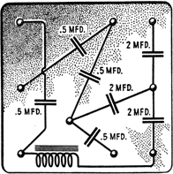
Figure 9—Internal connections of filter and by-pass condensers, and filter reactor
When replacing a pitch control coil, sometimes a similar condition will result. If after replacing a pitch coil it is found that the maximum range is not obtained by adjustment of the trimming condensers one of the following procedures must be used.
- Try several pitch coils. One may be found of the correct inductance for use in place of the defective one.
- If the range is low, that is less than 1100 cycles, try removing a few turns from the coil and readjusting the trimming condensers.
- Replace both the fixed condensers across the fixed and variable pitch oscillators with ones of a greater capacity. Replacing one without the other will not remedy the situation. Both must be replaced simultaneously.
(2) Removal Of Parts and Location of Cable
The cable that is used to connect the Theremin chassis and the S. P. U. is clamped securely in a definite place on the inside of the cabinet. Whenever any assembly is removed, and this cable is shifted from its position, it is very important that it be returned to its original position when the Theremin is returned to normal operation. Failure to have this cable in its normal position may result in inability to adjust the Theremin for normal operation.